We live in an increasingly interconnected world, one in which mobile communications provide a significant element of this interconnectivity. This increasing demand for high-speed, low-latency networks supporting mobile connectivity is leading the definition of fifth-generation (5G) mobile networks. These next-generation networks are driven not only by changing user demands such as video and cloud applications, but also by the Internet of Things (IoT) and Industrial Internet of Things (IIoT). Both of which introduce machine-to-machine communication, and in the case of IIOT, require reliable networks and low-latency response times for critical applications. 5G networks challenge network operators and equipment OEMs as different frequency bands across geographic locations and regulatory environments will present the need to support multiple air interfaces requiring adaptable solutions.
5G networks are, therefore, defined by their ability to provide increased reliability connections with a significantly reduced latency at an increased data rate, while providing greater capacity and support for an increased number of connections. To provide these defining elements, 5G networks and infrastructure require a radical evolution from currently deployed fourth generation (4G). To meet these challenges, 5G solutions must be able to provide the cornerstones of increased spectral efficiency and support for ultra-densification.
Increased spectral efficiency enables more information to be transferred within a fixed bandwidth—often called a channel. This helps to address the increasing demand for data rate and capacity. While ultra-densification provides a significant increase in the number of base stations and back-haul connections, it is proving the capability to implement these that drive the change in solution compared to current networks.
Current 4G network infrastructure presents several issues that limit its ability to scale and support next-generation networks. Typically, these consist of antenna arrays and connected radio heads mounted on now familiar cell towers. Depending upon the architecture, these towers may provide for an integrated radio head and antenna or a distributed approach. Increasingly, to provide better system performance and reduce loses in the coaxial cabling required for the distributed solution, an integrated approach is used.
However, even this integrated approach to the antenna array does not provide the capacity to implement 5G networks being unable to support the number of connected devices at the data rates required. Simply put, the tower cannot support the number of antennas required to support 5G infrastructure.
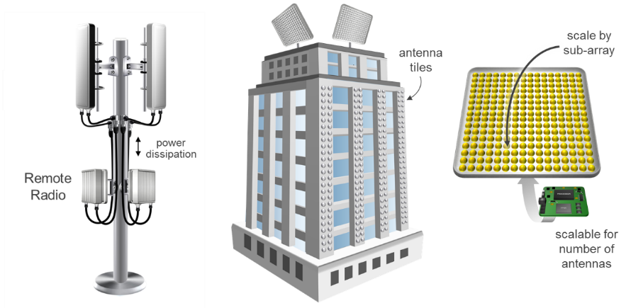
To address this, Massive Multiple Input Multiple Output (Massive MIMO) architectures are being considered to provide 5G network infrastructure. These consist of multiple antenna systems potentially of up to 1024 antenna. Massive MIMO, therefore, provides the ability to implement fine grain beam forming, enabling spatial multiplexing. This means that each of the beams can support the full bandwidth. As it is focuses the emitted energy within the beam, it offers increased RF power efficiency. Massive MIMO solutions also enable a message to be broken up and transmitted simultaneously over different paths using multiple antenna.
This change in antenna architecture allows for ultra-densification as antenna tiles can be deployed on buildings, structures and other parts of the surrounding infrastructure moving away from the cell tower. This is especially true if millimetre wavelength communications are used to provide the back-haul capabilities in place of a wired back haul. This change in antenna deployment also brings with it constraints on the radio unit connected to the antenna; constraining not only energy efficiency but also form factor and scalability to scale from small- to large-scale antenna deployments without radical architectural changes.
It is not, however, just the demands of the 5G infrastructure that present challenges. Network operators also bring constraints in the frequency planning. The frequency plan will vary from operator to operator depending upon their licensing and geographic location, but the solution must be configurable to support these use cases.
Embedded System Level Challenges
5G radio units, therefore, face several challenges in their design to ensure scalability and power efficiency. To support small antenna deployments, the core of the radio architecture must be tightly integrated to be able to connect with a small number of antennas at high data rates. The traditional approach to this challenge would be the combination of a multi-giga sample ADCs and DACs with a System on Chip (SoC). This approach provides the ability to perform the embedded system design; e.g., virtualization, CloudRAN, etc., within the SoC processor cores, while the programmable logic within the SoC is used to implement the ADC/DAC interfaces and signal processing pipeline.
Such an approach however, requires significant board space to implement the SoC with its supporting peripherals, and the analogue front end containing the DAC and ADC. To ensure RF performance is not compromised, separation between devices must be maintained along with following stringent and time-consuming layout rules. The more channels required in the solution the more complex addressing the routing signal and power integrity becomes. Solving this increases the form factor of the solution. To address the increased operating bandwidths required for direct conversion, many data convertors implement interfaces, which use JESD204B. These interfaces bring with them multiple issues in the design. JESD204B interconnects take FPGA resources and increase the power dissipation of the solution.
This distributed solution, therefore, presents an increased power dissipation. Typical high- performance ADCs may require 2.25 W while DACs would be in the order of 1.75 W, in addition to the power dissipation of the JESD204B transceivers. This not only increases the board space required, but also increases the power dissipation of the overall solution. The additional steps required in the design of the solution increase both the time taken for development—increasing the non-recurring engineering and development costs—along with manufacturing and bill of material costs.
To solve the challenge presented by the network operator licensing and geographical restrictions, the use of direct RF sampling reduces the analogue front-end components required. Direct sampling is enabled by using ADC and DAC devices with a high sampling frequency and a wide analogue input bandwidth, allowing the RF signal to be directly sampled. This removes the need for analogue front end, which down convert the signal into the ADC sampling window. These analogue front ends are also not programmable or easily adaptable to support licensing or geographic restrictions, which requires OEMs to use different frequency bands. Designing these analogue front ends requires specialized skills in the design and careful consideration of the component selection, placement and routing. The designer must also consider component drift with aging and temperature. Direct sampling removes the need for many of these components allowing the processing to be performed within the digital domain. However, it does come with a trade-off, in that higher sampling discrete ADC and DAC required to directly sample the RF signal have a higher power dissipation.
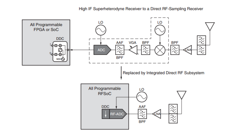
The solution to these design challenges is to leverage even tighter integration, advanced CMOS technology to reduce power dissipation and allow analogue to leverage Moore’s Law. This is achieved by integrating the ADC and DAC devices within the SoC. Such integration provides for a more optimal solution, targeting massive MIMO applications.