Growing in popularity for many automotive sensor applications, the SENT (Single Edge Nibble Transmission) bus is designed to transmit readings from devices such as temperature, flow, pressure, and position sensors. It is unidirectional and runs at relatively low-speed and high amplitude and encodes precision measurements in pulse trains. These characteristics make it robust and easy to integrate, but communications can still be affected by noise, timing issues, and subtle differences in implementations.
Unlike basic protocol analyzers, oscilloscopes equipped with protocol decoding, can be used to see both the decoded SENT bus traffic, as well as signal quality. This ability to see bus signals and decoded traffic makes oscilloscopes useful for visualizing overall system operation and for troubleshooting problems at the system level. Automobiles rely on extensive networks of sensors, actuators and displays, and many problems involve bus timing relative to I/O events or values. The ability to look at I/O signals and bus transactions at the same instant is critical to tracking down the root cause of a problem and system-level debugging.
Also known as SAE J2716, SENT is used for communication between power-train sensors and Electronic Control Units (ECUs). SENT provides higher precision than analog PWM techniques and, at 30 kb/s, has a higher data rate than LIN. A typical SENT transmission is shown in Figure 1. The physical layer of the SENT interface consists of a signal line, a +5 V supply voltage line, and a ground. The signal line logic levels are low < 0.5 V and high > 4.1 V.
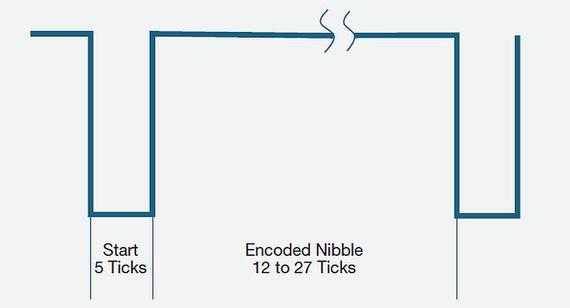
SENT transmits data in 4-bit nibbles between two falling edges as shown in Figure 2, hence the name “Single Edge Nibble.” Timing of the SENT bus is measured in ticks, with each tick typically 3 μs wide. Each nibble starts with a logic-low period of at least 5 ticks, followed by a variable length logic-high period representing the encoded data value. A 0000 binary data value is represented by a logic-high duration of 12 ticks. A 0001 binary data value is represented by a logic-high duration of 13 ticks, and so on, up to a 1111 binary data value is represented by a logic-high duration of 27 ticks.
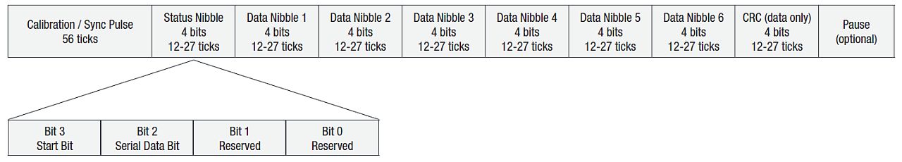
The SENT bus has a distinctive ability to transfer data at two different rates simultaneously. The primary data is normally transmitted in what is typically called the “fast channel” with the option to simultaneously send secondary data in the “slow channel.” A SENT “fast channel” message begins with a sync pulse where the time between successive falling edges is 56 clock ticks. The SENT message is 32 bits long, consisting of:
- 4 bits of status/communication information (12-27 ticks)
- Six, 4-bit nibbles of data (representing one or two measurement channels, 12-27 ticks per nibble)
- 4 bits of CRC for error detection (12-27 ticks)
Optionally, a 20-bit message (where the 12 data bits represent one measurement channel) can be sent, followed by a pause pulse, resulting in the same overall message rate. For example, when two 12-bit fast channels are used, the transmission looks like that shown in Figure 3.

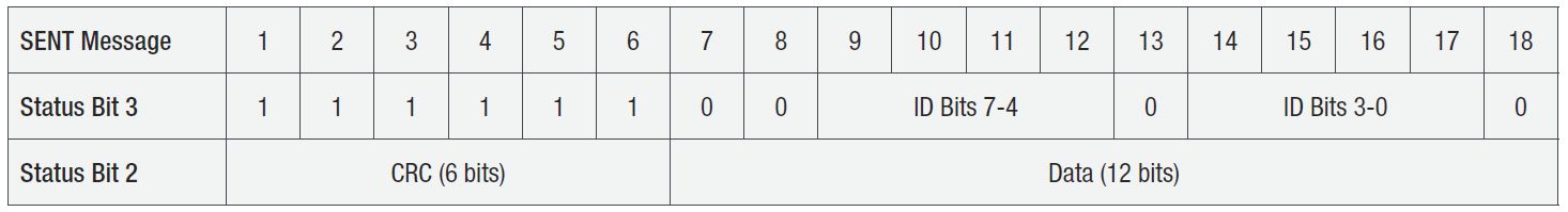
In the “slow channel” data is transmitted 1-2 bits at a time via bits 2 and 3 of the 4-bit status/serial communication nibble in 16 or 18 successive fast channel messages. These bits are accumulated to build the slow channel message. For example, the “Enhanced Serial Message with 12-bit Data and 8-bit ID Format” is identified by the initial bit pattern “11111100” and transmits an 8-bit ID value, a 6-bit CRC, and a 12-bit data value:
Test setup
The SENT bus is a single-ended, ground-reference signal. Although most oscilloscopes can acquire and display the bus using standard single-ended probing, the signal fidelity and noise immunity can often be improved by using differential probing.
The same pulse-width encoding that makes SENT so robust, also makes it difficult to interpret on an oscilloscope. Decoding software running on the scope greatly simplifies interpretation. For an oscilloscope equipped with SENT decoding and triggering, you start by entering the necessary parameters to enable the oscilloscope to decode the packet. These typically include:
- Input channel
- Voltage threshold
- Signal polarity
- Number of fast channels and channel format
- Number of slow channels and channel format
- Pause pulse
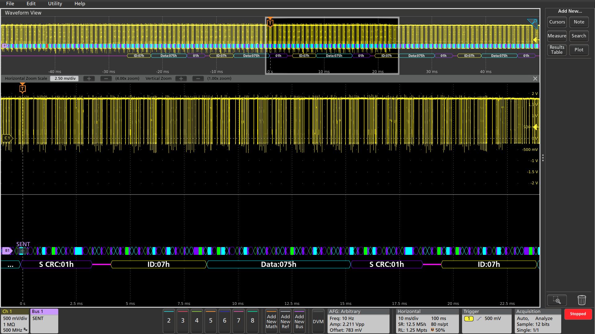
Once the oscilloscope with SENT decoding is configured, it will be able to display the bus. A time-correlated waveform and bus decode display is a familiar and useful format for many hardware engineers. As shown in Figure 5, the decoded bus waveform indicates various elements of SENT messages. In this case, both fast and slow channel packets are shown in a single waveform display, with the slow channel packets shown below the fast channel packets.
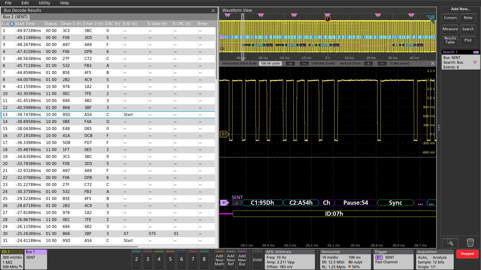
For firmware engineers, a more comprehensive results table format may be useful. As shown in Figure 6, such a time-stamped display of bus activity can be compared to software listings and allows easy calculation of execution speed.
When the SENT bus contains both fast and slow channel data, the results table view provides side-by-side readouts of the two data channels. Since the slow channel data is spread across 18 successive fast channel packets, there are 18 fast channel messages from the start to the completion of the slow channel data message. In this example, the table is also linked to the waveform display for additional analysis.
SENT bus trigger and search
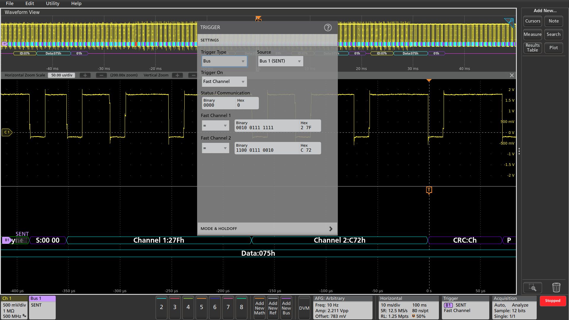
When debugging a system based on one or more serial buses, one of the key capabilities of the oscilloscope is isolating and capturing specific events with a bus trigger. When the bus trigger is correctly set up, the oscilloscope will capture all the input signals and one specified bus event will be positioned at the trigger point. The example in Figure 7 demonstrates triggering on status value of 0000 binary, fast channel 1 data value 0x27F, and fast channel 2 data value 0xC72.
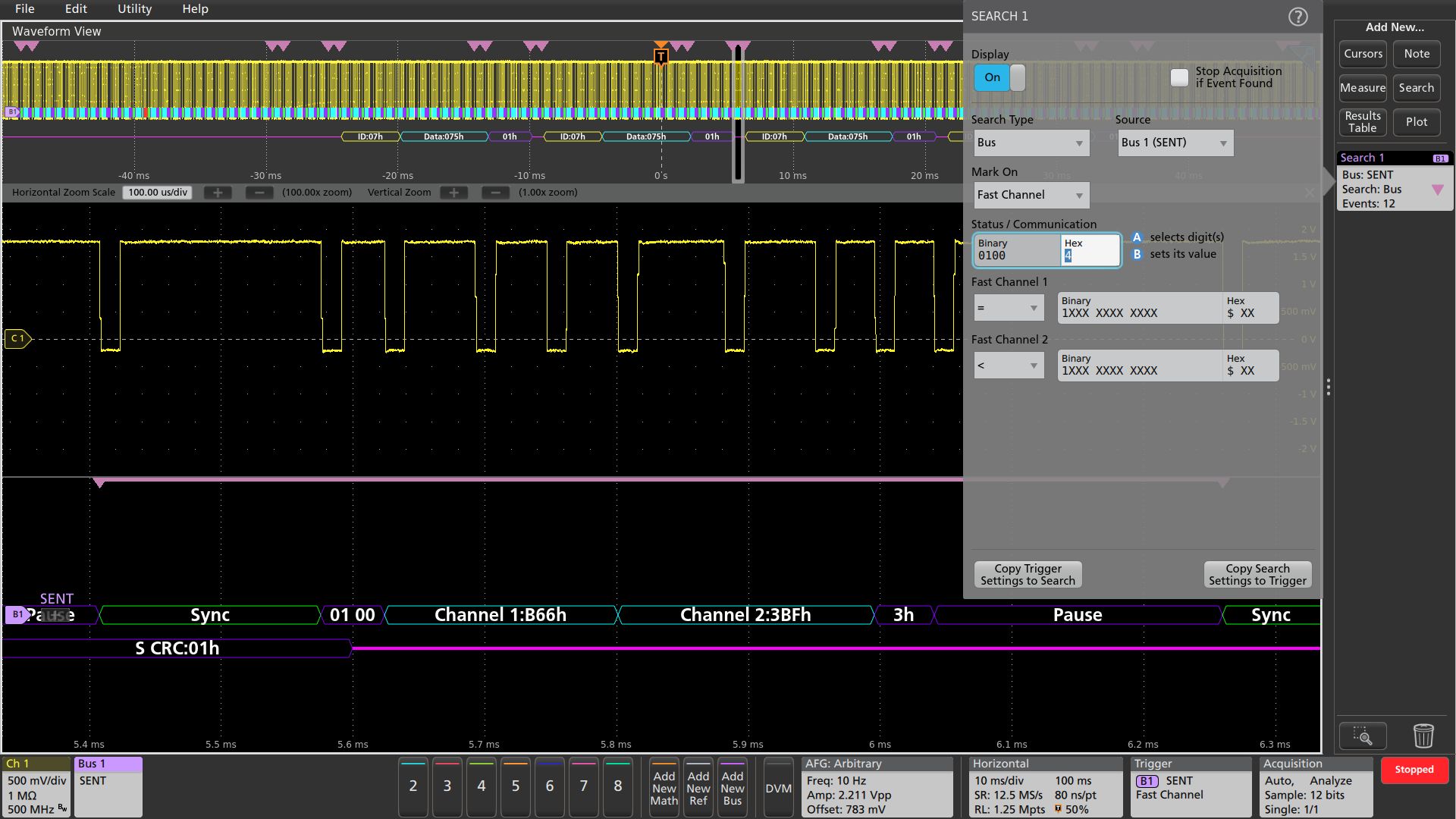
Another useful technique is to use the oscilloscope’s search functionality to find all the bus events that meet search criteria and determine how many of them occurred. The setup is like the bus trigger setup and allows the oscilloscope to find and mark all of the specified bus events.
In the example in Figure 8, the automatic search is looking for specified fast channel data values. This data pattern occurred 12 times in the acquired waveforms and the positions of the specified serial data packets are shown with the pink bracket icons. In addition to fast channel search, other searches commonly performed in SENT bus analysis include start of packet; slow channel searches to determine when a specified message ID or specified slow channel data value occur; pulse pauses of a specified duration; and instances when an incorrect frame length or incorrect CRC value occurs.
While the SENT bus is growing in popularity for many automotive applications, SENT bus communications can be affected by noise, board layout, reset issues, and subtle differences in implementations. As we have seen, oscilloscopes offer powerful capabilities for quickly and efficiently tracking down the source of problems and validating designs. Unlike basic protocol analyzers, oscilloscopes equipped with protocol decoding, can be used to see both the decoded SENT bus traffic, as well as signal quality for a complete system view.